PI4CC
|  |
Switch and phase unit details
The switch unit is simple It have to choose 2 antennas in-line and connect them to the output labeled ANT1 and ANT3.
Furthermore it will put up voltage on the coax to feed the RX-amp. There are leds added to see witch relais is active.
I have chosen to put the RF chokes in the same enclosure and solder the RG179 direct to the PCB, but a female F-connector can been solderd on the PCB.
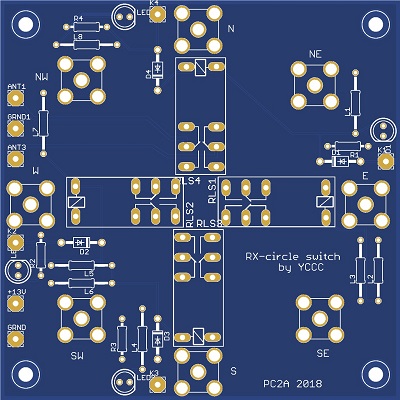 |
The pcb layout switch unit. The size is100 mm * 100 mm The value of each component is written in the BOM |
|
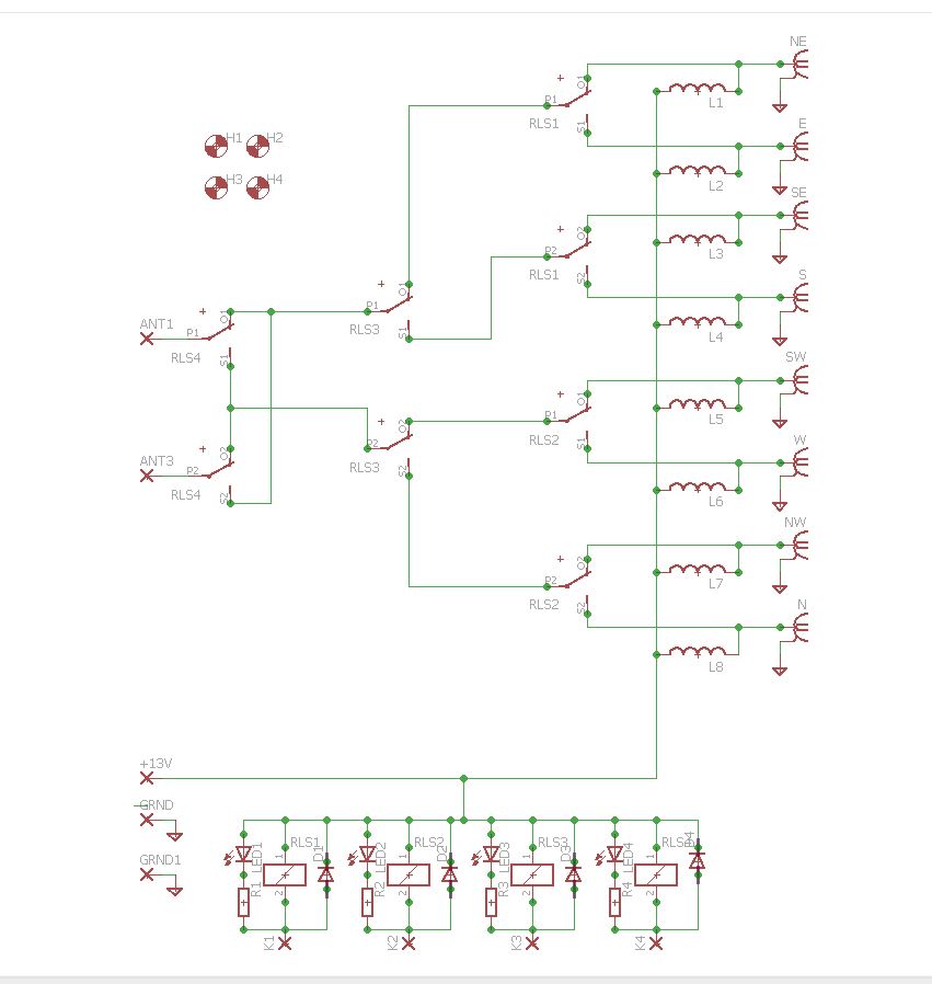 |
The schematic of the switch unit. |
|
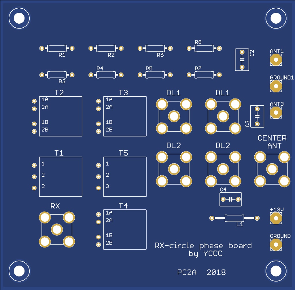 |
The pcb layout phase unit. The size is100 mm * 100 mm |
|
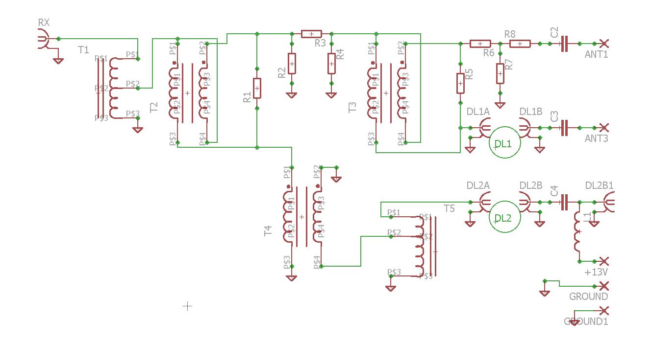 |
The schematic of the phase unit. |
|
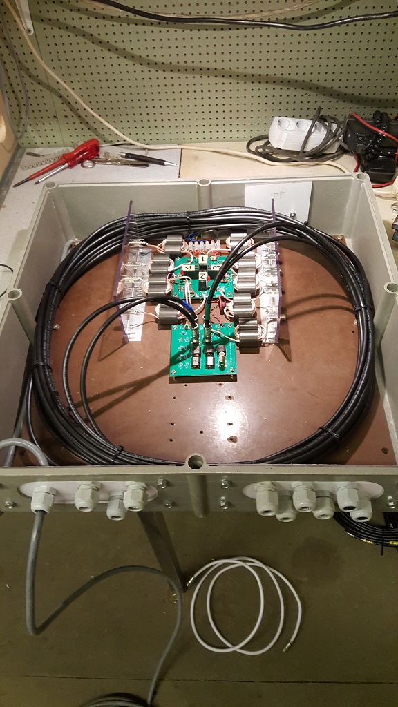 |
The complete enclosure with switch and phase unit, 2 delay lines and RF chokes. |