PI4CC
|  |
 class="img-responsive img-rounded" alt=""/> class="img-responsive img-rounded" alt=""/> |
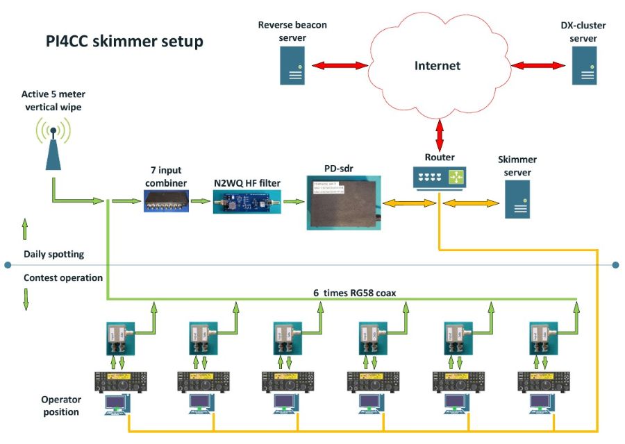
PI4CC has its own skimmer server running and it feeds the reverse beacon project. During daily operation one vertical antenna is used to put hf in to the HD-SDR. When one ore more K3 radio 's are active, it can feed the SDR with the current big antennas used at a particular band via a 3 db splitter on the back of the K3. |
|
 |
An overview of the complete skimmer setup. |
|
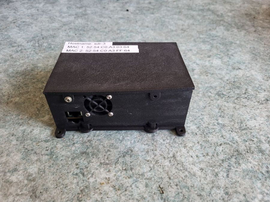 |
The SDR is build around a QMTECH ZYNQ7000 XC7Z020. Pavel Demin has build a HF frontend and wrote the needed software.
More info on the SDR via this link |
|
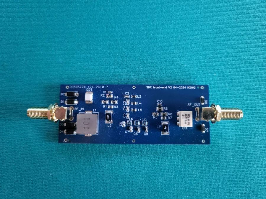 |
To protect the SDR from strong signals at the lower HF bands, N2WQ has developed a high pass filter to protect the higer frequenties for overload.
More info via this link |
|
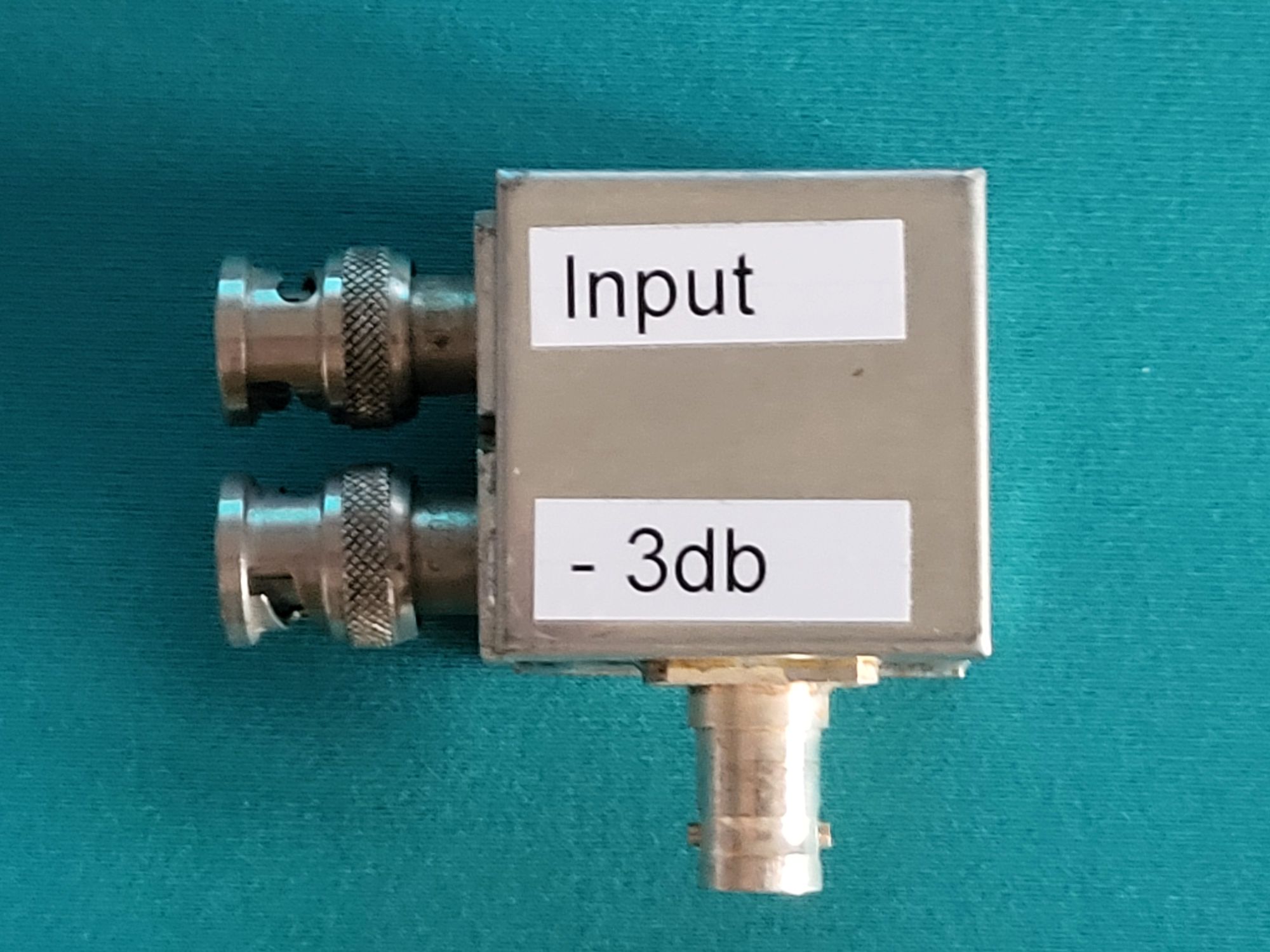 |
Via the RX out and RX in at the black plane of the K3 we can reroute the HF signal from the main antenna to 2 times a -3db signal. One is used to feed the K3 receiver and the second the SDR. The splitter is build around a minicircuit splitter named ADP-2-1 |
|
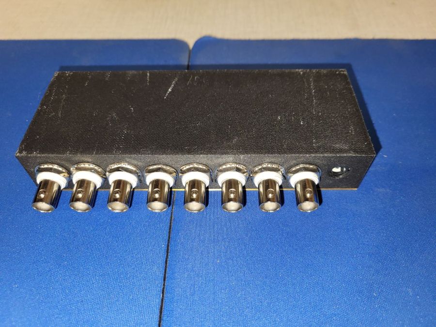 |
Via an active combiner we put all signals together to feed the sdr. A PDF with the schematic is here. |