PI4CC
|  |
 |
The 80 meter band is relatively "wide". It spans 3,5 ... 3,8 MHz, so the band width is almost 10%. To maintain an acceptable match without tuning, the radiator diameter/length ratio can be increased by using a "cage" instead of a single wire. This can be constructed using 4 wires, spread by plastic hoops. It gives an SWR of less than 1.5 across the whole band. Some pictures show a previous version. As always, we made sure that the feed point is perfectly symmetrical, and is perfectly matched to 50 Ohms. Some construction details:
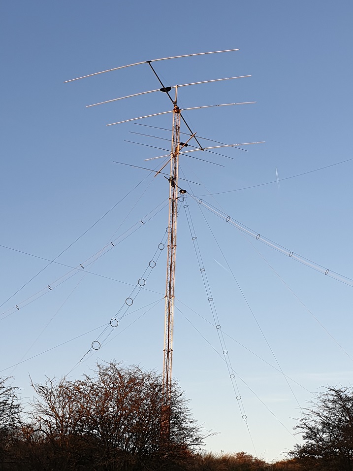
The latest project is a "turnstile" circularly polarised antenna, formed by 2 dipoles at square angles. This takes advantage of the XO refraction of the ionosphere for Near Vertical Incident Skywave (NVIS) propagation, which is most pronounced during daylight. In short: circular polarisation in the proper direction increases the signal strength by approx. 3 dB, and in the opposite direction by some -15...-20 dB. A publication in QST dec 2010 written by KL7AJ gives more information on this subject. The subject of NVIS is explained in great detail by Ben Witvliet PE5B, summary here. Furthermore, Jan Simons PA0SIM, has a great website on XO mode propagation. An example of practical implementation for a 700 kW MW transmitter can be found at Bernd Warniewski, which was our inspiration to build 2 identical dipoles. |
|
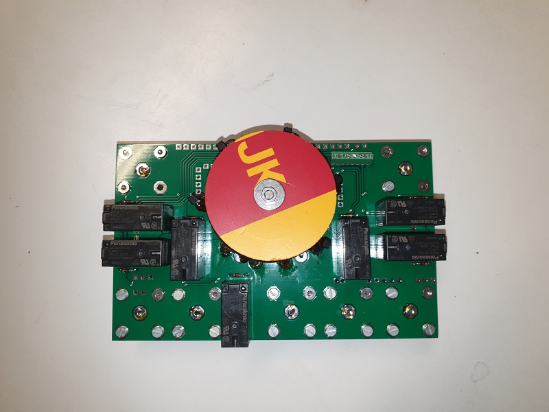 |
Each of both dipoles has an exactly equal-length coax cable down into the bunker. The circular polarisation is achieved by feeding them with a -90 or +90 degrees phase difference, using a coax delay line of 1/4 electrical wave length. And of course, the dipoles can also be used as stand-alone. To properly switch between all possibilities, a PCB relay board was developed. The modes are:
In the circular modes the 50 Ohm antenna impedances are in parallel, resulting in a load of 25 Ohm. This is transformed back to 50 Ohm by an autotransformer of 17 turns with a tap at 12 turns (ratio is 17^2 : 12^2 = 289:144 = 2.007:1), wound on an FT240-43 core. |
|
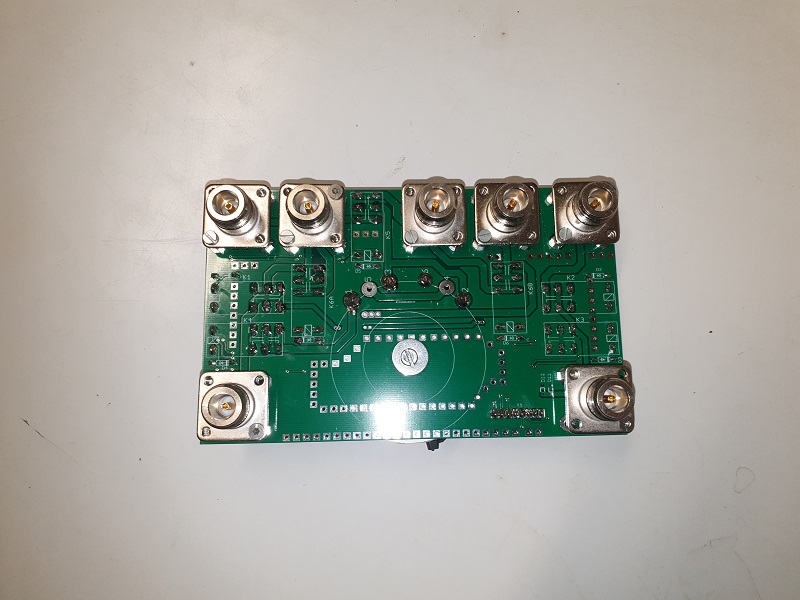 |
The PCB was designed to have 50 Ohm traces. With the FT240-43 core, it gives a perfect VSWR=1.02 response between 1 and 10 MHz. If you want to use the same board for higher frequencies, just use an FT240-61 core instead. |
|
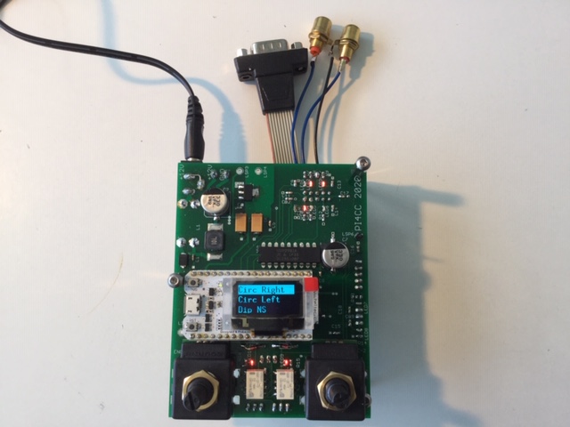 |
The relay-PCB is controlled from the shacks by an ESP32-based Heltec development kit. Note that the polarisation must be swapped between Tx and Rx, so it needs a PTT input from the transmitter. For this controller, a second PCB was designed from this schematic. The small Heltec boards cost about $11 at Ali. They have a little OLED display, which is fine for a few words in a menu. The mode is selected by a rotary encoder, so the operator can very rapidly scan through all antenna combinations without looking for buttons. Good for contest work! The second rotary encoder is spare. In the future it might be used for selecting the direction of the 9 Circle RX antenna, which can be connected as diversity Rx input. The program drives an output buffer UDN2981A, that outputs +12V to the relays via an 8-wire UTP cable. The antenna relays should only be switched when there is no RF power. When a debounced PTT signal comes in, a sequence will 1) swap polarisation, 2) short-circuit the diversity-Rx input and wait for a confirmation, and 3) set PTT output to the PA. The whole switching procedure takes some 15 ms, which is also fine for CW. See page 2 of the schematic for a timing diagram. Programming of the Heltec kit can be done from the well-known Arduino development environment. This little kit comes with a huge amount of examples, and also libraries for parallel asynchronous programming, using both ESP32 cores. Our program is split in parallel tasks for encoder readout, switching, and display. Presently, we are still in the experimental stage. In the future, the progam file will be made available as a download. Of course we ordered a few more PCB's than we needed. As soon as our system is fully tried and tested, these will also be made available for hams who are interested via our webshop. Note that this is not a commercial undertaking, but just a way of facilitating the hobby! |