PI4CC
|  |
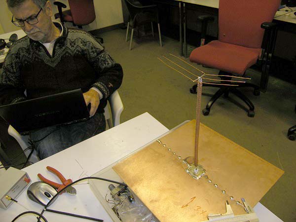 |
Some scale modeling was done at about 450 MHz with a VNWA to verify the MMANA calculations, in particular the effect of "fat" radiator and top loading. Various radiators were tested, with length/diameter ratios in the range of about 210....11. The copper plate on the photo represents the ground. These scale models perform amazingly well, even inside the bunker.
|
|
 |
We measured soil conductivity as well, which confirmed that the dunes behave as a relatively poor conductor. Fortunately, MMANA applies these ground properties by default. |
|
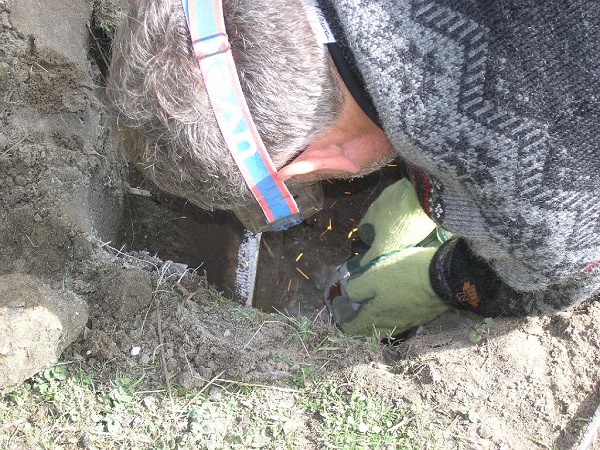 |
The first step was making an electrical connection to the bunker rebar, which has a top area of is about 15 by 30 meter. Here is Ed is welding a "ground rod" to the rebar. |
|
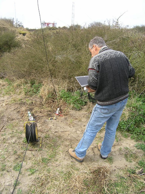 |
Ground resistance was measured. It proved to be relatively low, which is good. As a first test, a single vertical wire of about 18m was connected. On the first CQ on 80m the RBN reported 8 dB S/N in Australia. Next, we worked VK0EK on 80m almost immediately.A video of this QSO is on line. The TL tube clearly shows the antenna current - proving that this current also flows into the rebar.
|
|
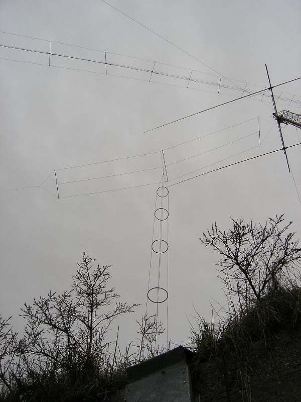 |
Here is a view of how it will look in the near future.
A choice was made for a square 4-wire cage type radiator of about 16.5 x 0.5m, plus a top load akin the famous Radio Veronica ship. |
|
 |
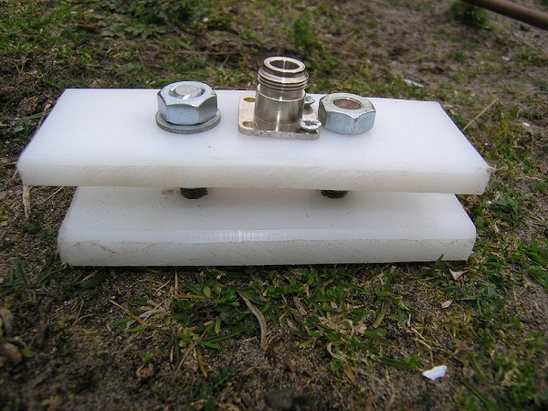
As the calculations show that the construction will work for both 160m and 80 m (being shorter and longer than 1/4 wave respectively), the idea is to make 2 different matching networks to match the antenna to 50 Ohms on both bands. The photo shows the finished match box, which starts with a 50:50 Guanella balun to force symmetrical currents and hence prevent radiation from the coax. Followed by a relais to select the frequency. Left is 80M and right 160M At the top a relais. This relais follow the lower relais. The center wire is the groundbus.
|
|
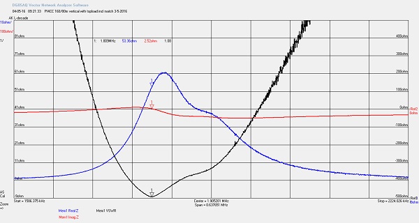 |
A first plot with the 160M match in place. A complete overview of the work done so fare. Photo's will be updated the upcomming weeks. Last update 16-7-2016.
|